Flow System Installation for Water Treatment Works
The Project
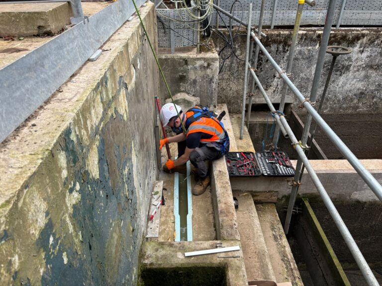
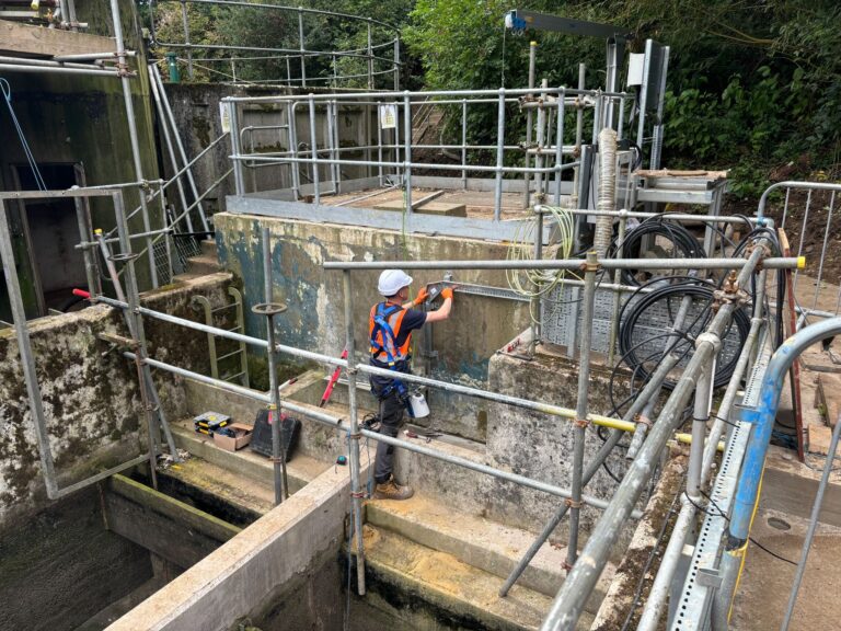
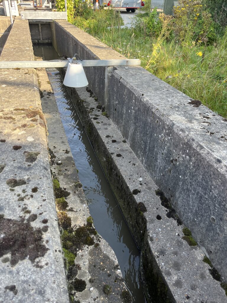
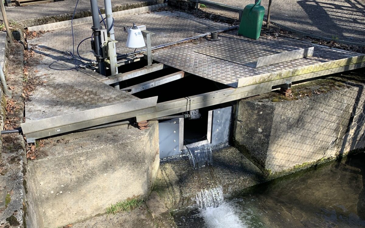
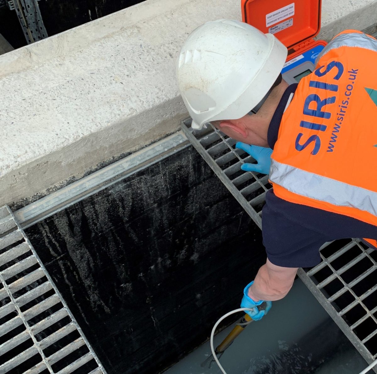
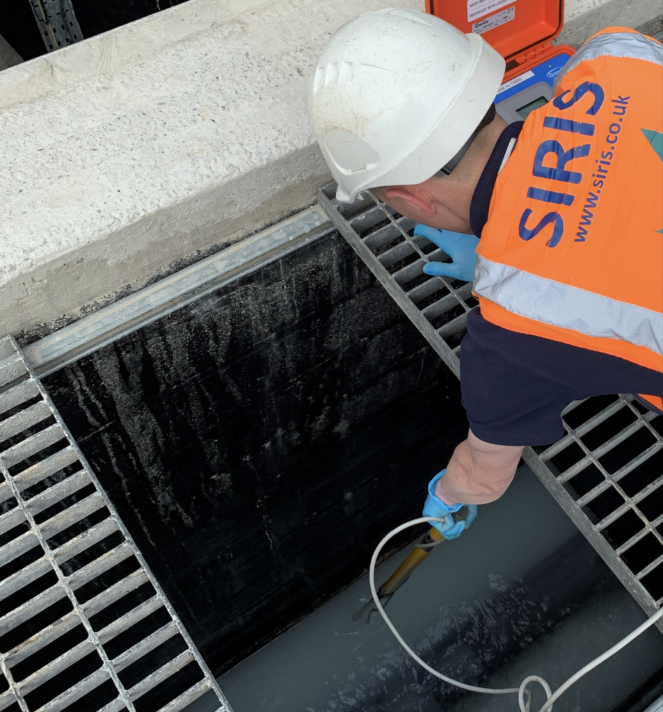
This summer, our team installed a flow system at a Water Treatment Works site.
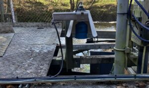
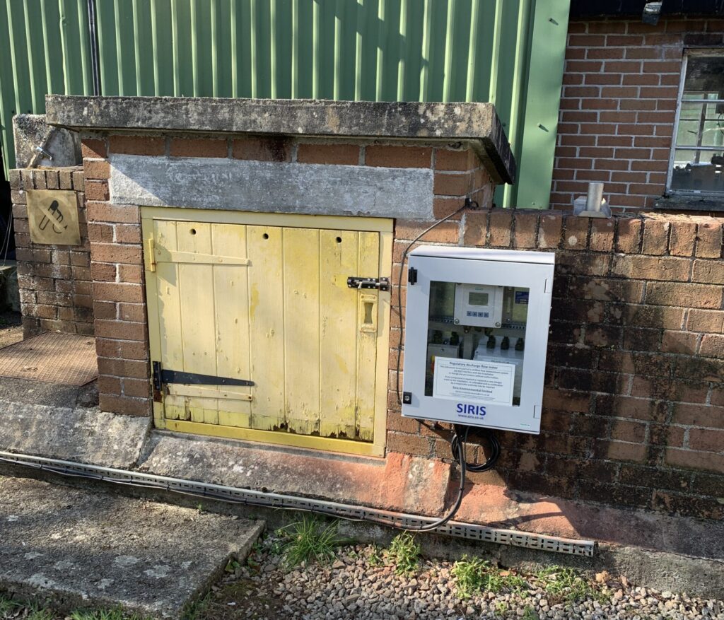
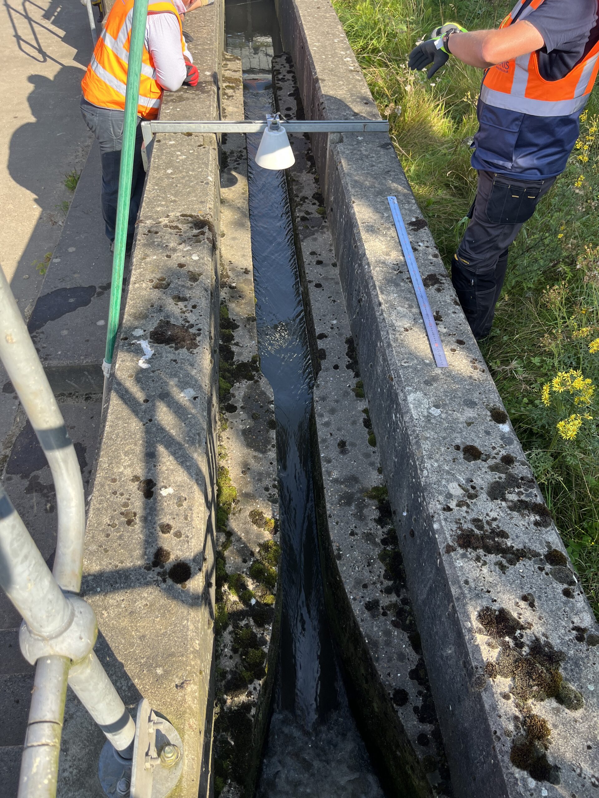
Jamie, our Trainee Service & calibration Engineer and Jordan, our Servicing & Installation Engineer, installed a new stainless steel cross-channel bracket.
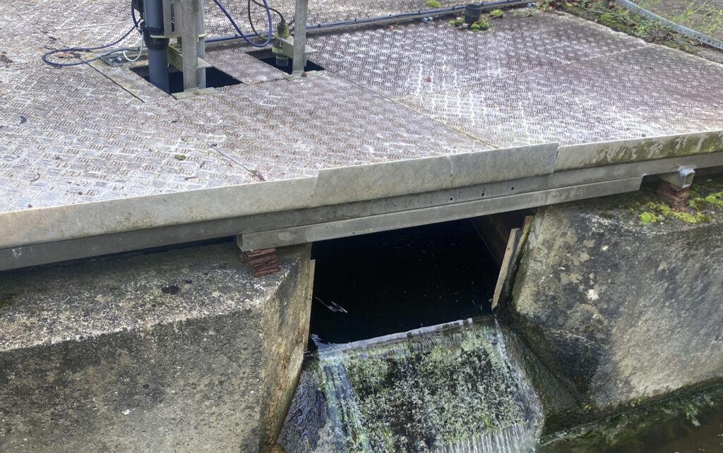
On this bracket, our team were able to mount the ultrasonic sensor over one of our 70b flume channels, so that more accurate and reliable data could be gathered from the open channel flow below.
Additionally, we fitted cable trays to the wall, allowing the sensor cable to run above ground and into a SIRIS Open Channel Ultrasonic Flow Meter, which we installed and calibrated accordingly. Now up and running, this system – with this particular application – can handle flows of up to 12.42 litres per second and is ready for its mCERTs inspection.
Why is an accurate flow system installation important?
If your site discharges – or plans to discharge – wastewater (also known as trade effluent) into the public environment, you will need a consent to discharge from your local water company, which outlines the conditions under which you are able to discharge, including your volumes of flow. Failure to adhere to these permit conditions could result in charges or even prosecution. With SIRIS Environmental, our expert team ensures your installation stays within permitted regulations for accurate monitoring and you can be confident in a system that will meet your mCERTs requirements.
The installation of an effective flow monitoring system also allows you to accurately track the amount of effluent your site discharges, which could reduce your wastewater charges and help you understand and reduce the volume you discharge into the environment.
Learn about our Open Channel Ultrasonic Flow Meter range
A local wastewater plant client had concerns over the ability of their incumbent flow meter system to meet flow demands. The inlet was estimated at some 40+ years old and the profile of the local community that it served had changed considerably during this time. Greater levels of effluent now needed to pass through the inlet safely and be recorded accurately. There were identified concerns about existing measures in place to meet Flow Pass Forward and stormwater monitoring requirements.
Testing Planning
The originally-tested capacity of the flume was 45L per second, but the system now needed to be tested for flow of up to 64L per second to meet its potential demand.
Our team were tasked with testing the flume and flow monitoring system to ensure that it could cope with the increased demand and to check for multiple potential calibration risks – given the flume was now required to be utilised above its official design criteria. In particular we tested for:
Poor flow control within the flume: Checking that turbulence did not increase above levels required for reliable metre readings and that the current system would be suitable for higher flows.
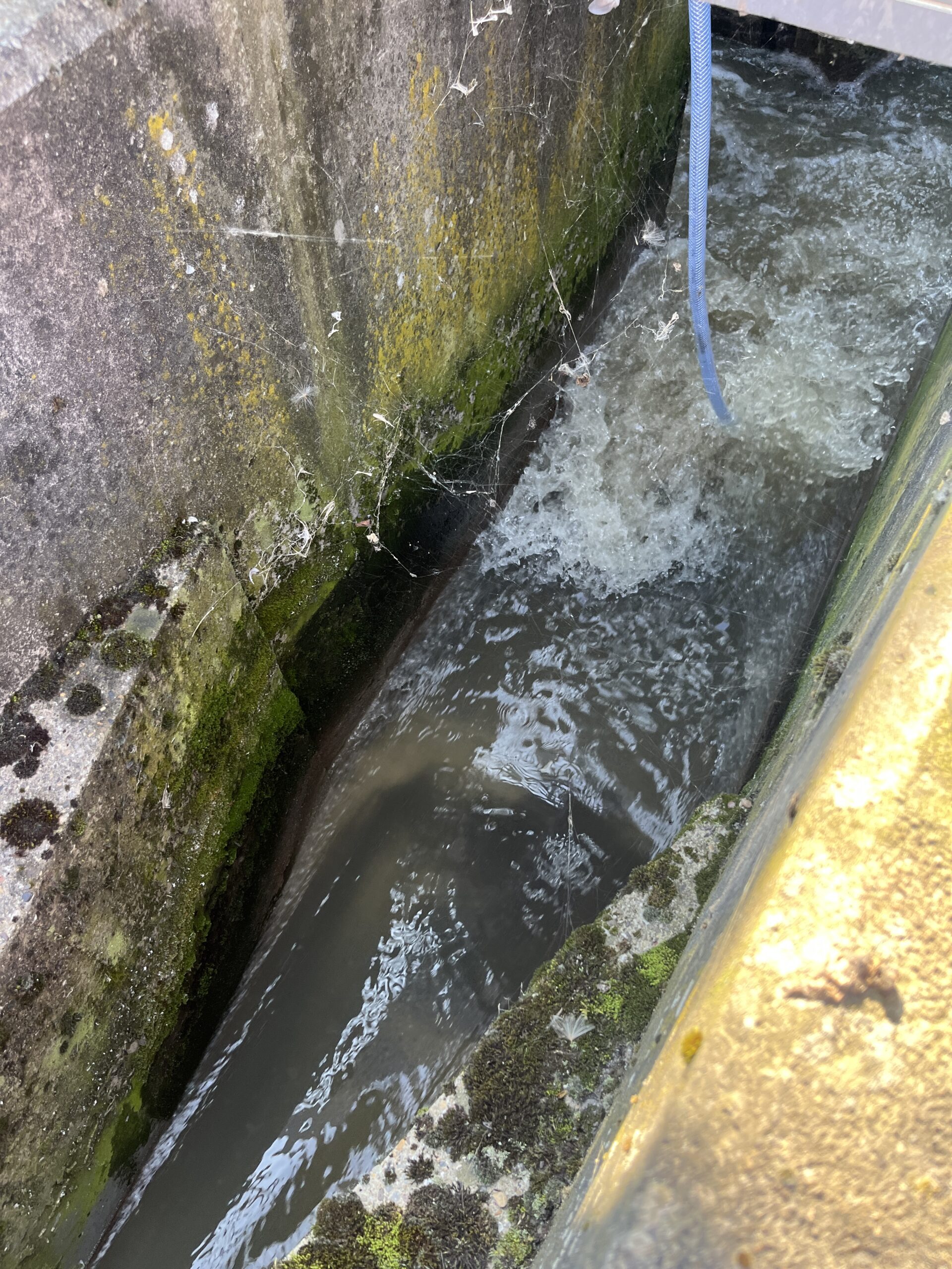
Ensuring free flow discharge conditions: Checking and verifying that flow would not go into drown conditions under increased pressure, which would risk inaccurate readings and compromise the entire system. A flume reaches a drowned state when the flow out of the flume is restricted to the point where the free flow discharge equation is no longer valid, over-indicating the measured flow rate.
Testing Completed
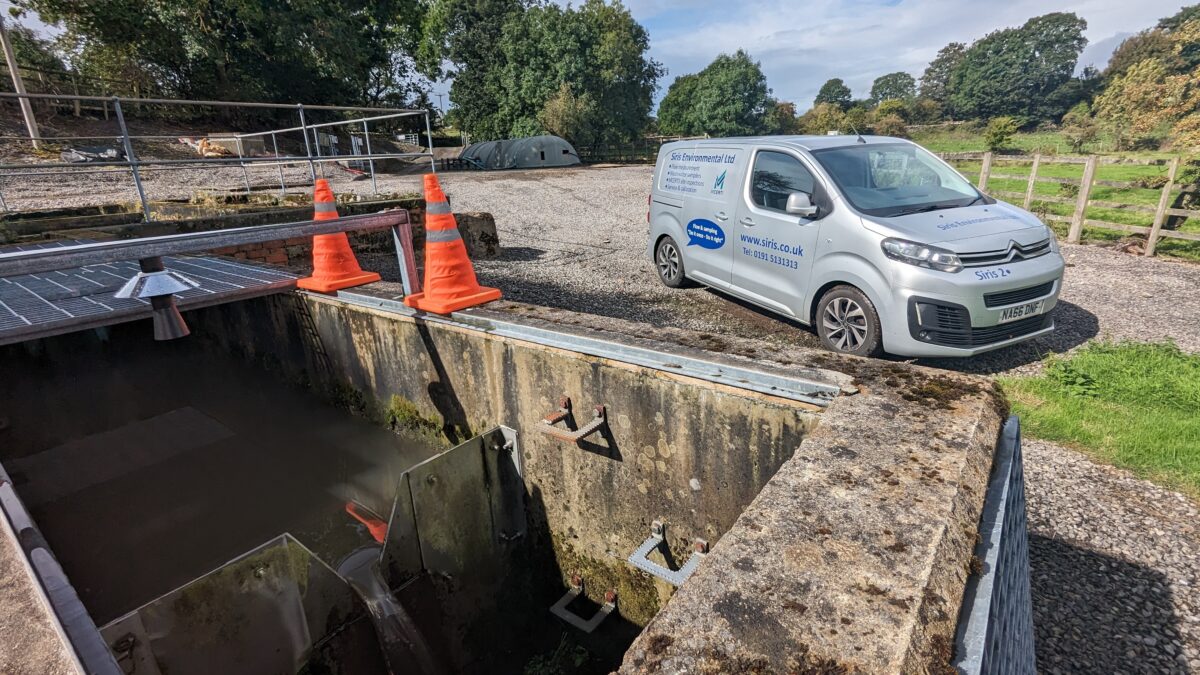
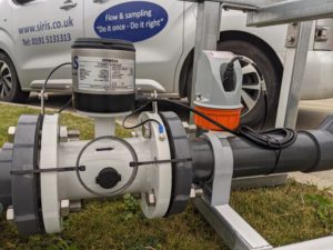
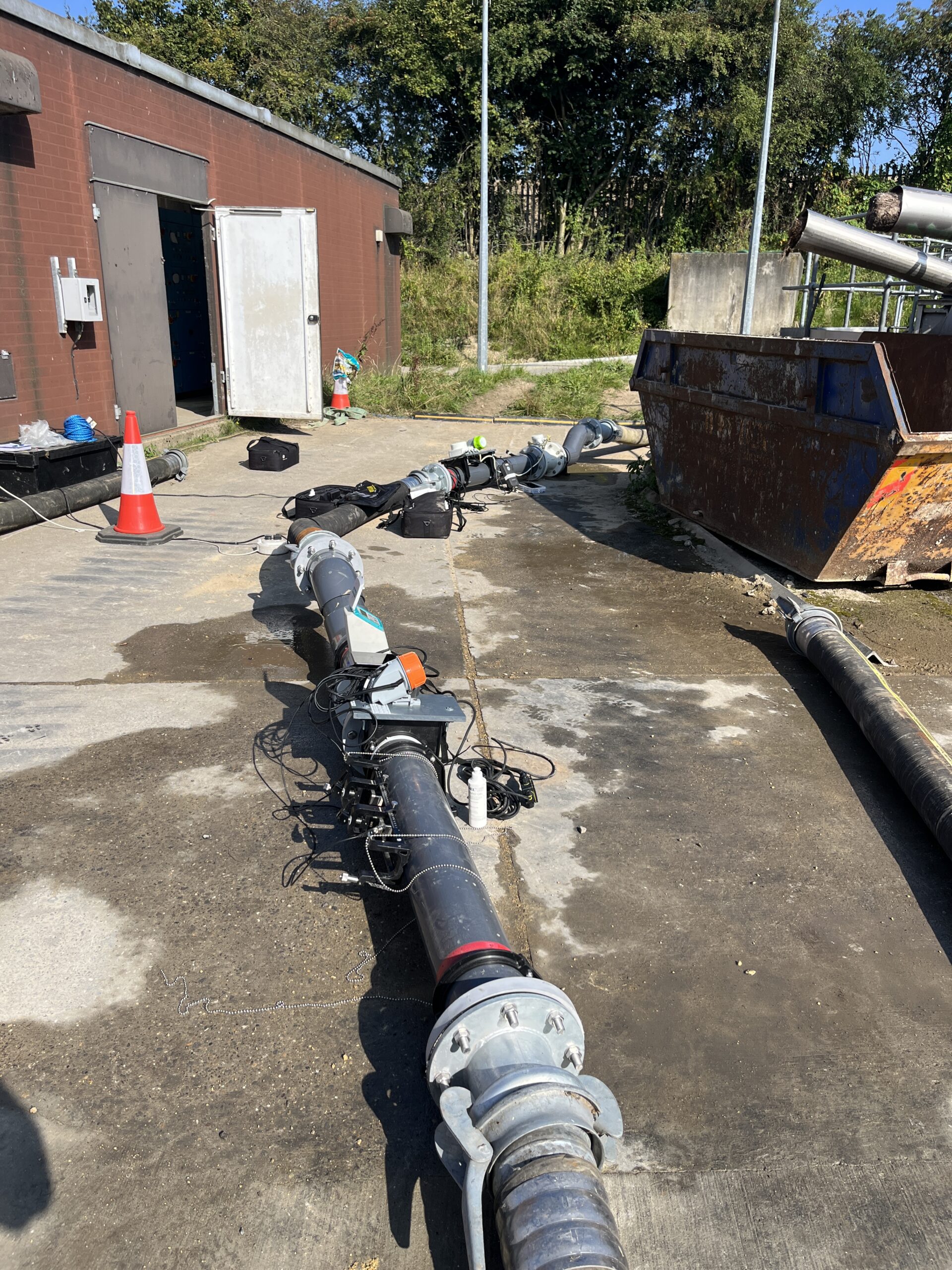
Our testing equipment included 2 electromagnetic flow metres that we incorporated into the works to monitor flow capacity and rates. We also blocked off the storm overflow system as this is only to be used for discharge in genuine environmental cases. We then tested the flume at varying flow rates, with the following outcomes:
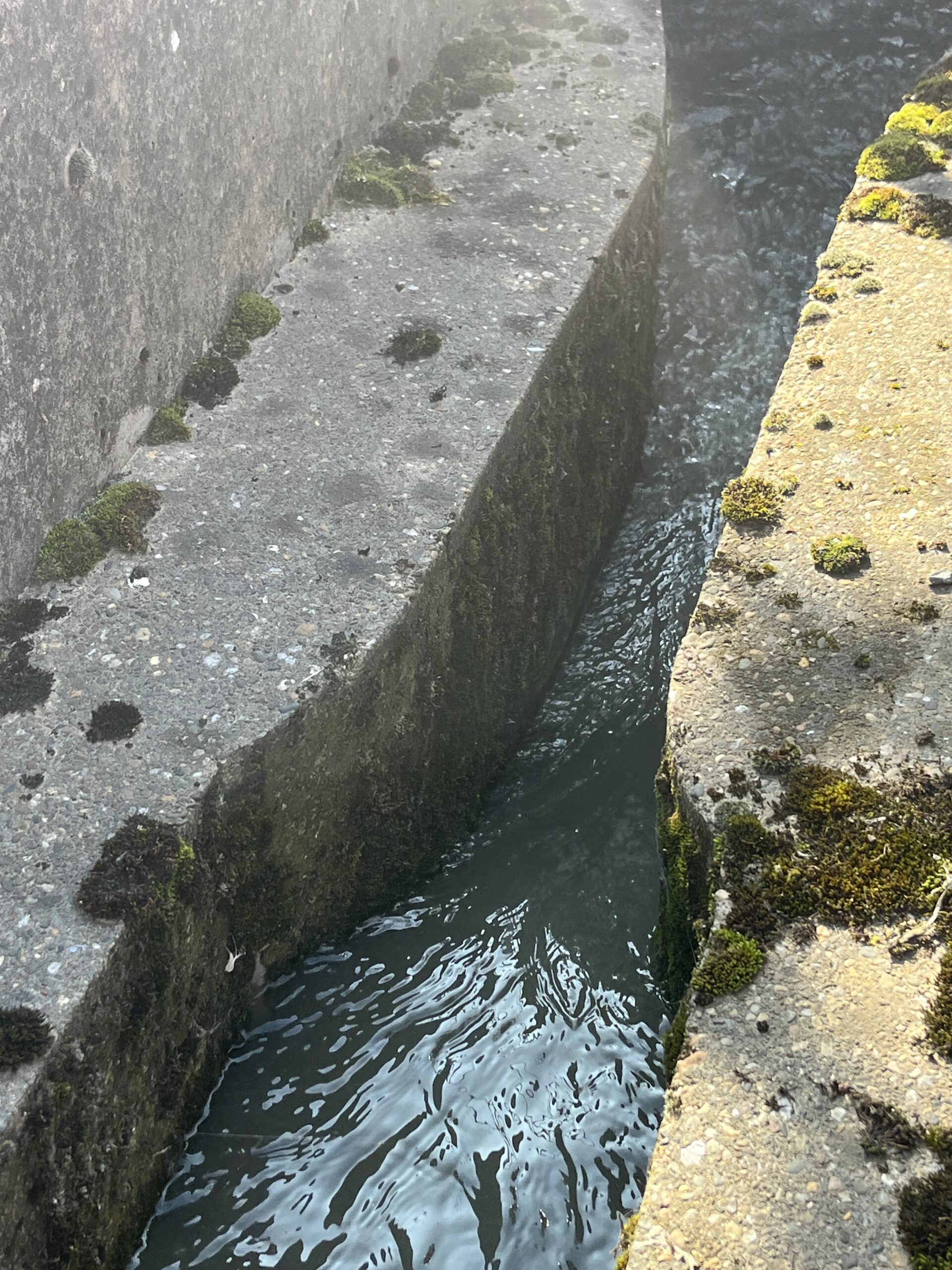
In the video below we can see 50L per second flowing well and the final effluent is clean and slightly above the current normal
69L per second again showed controlled conditions and was just above what the client processing requirements
We then increased the flow to 73L per second, at which point the effluent started to move into a drowned state
Finally, at 76L per second, we witnessed a definite drowned state
The Outcome
Using our expert teams, we were able to use accurate testing conditions, calibration expertise and appropriate equipment to allow for a high level of confidence in the ability of the inlet capacity to cope with the increased flow demands.
We were able to pass the flume as being suitable to cope with the increased flow while maintaining accuracy levels, meaning the inlet did not need to be replaced and we can continue to service and inspect as appropriate.
Is your system able to cope with its current requirements?
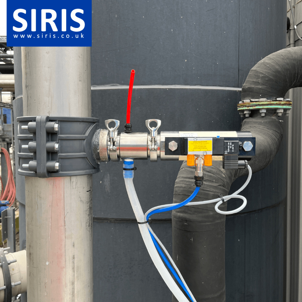
Our brewery client had expressed an interested in developing their existing flow water monitoring system into a more comprehensive solution – including a potential sampler.
Work Completed
We carried out a site analysis of client requirements and suitability for the addition of a wastewater sampler within their final solution.
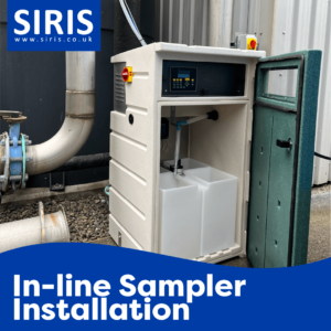
After identifying a suitable product and location we were able to specify, design and install an in-line sampler suitable for their needs.
All testing and verification was completed on the final installation by our expert projects team.
The Outcome
Our client is satisfied with their solution and now able to extract event more data about their wastewater to feed into their business information systems.
Product Shot
Product Shot
Require a sampling system?
Our team has the solution for you. Talk to us today.
CASE STUDY: FLOW SYSTEMS INSTALLED IN FOOD FACTORY
The Client Needs
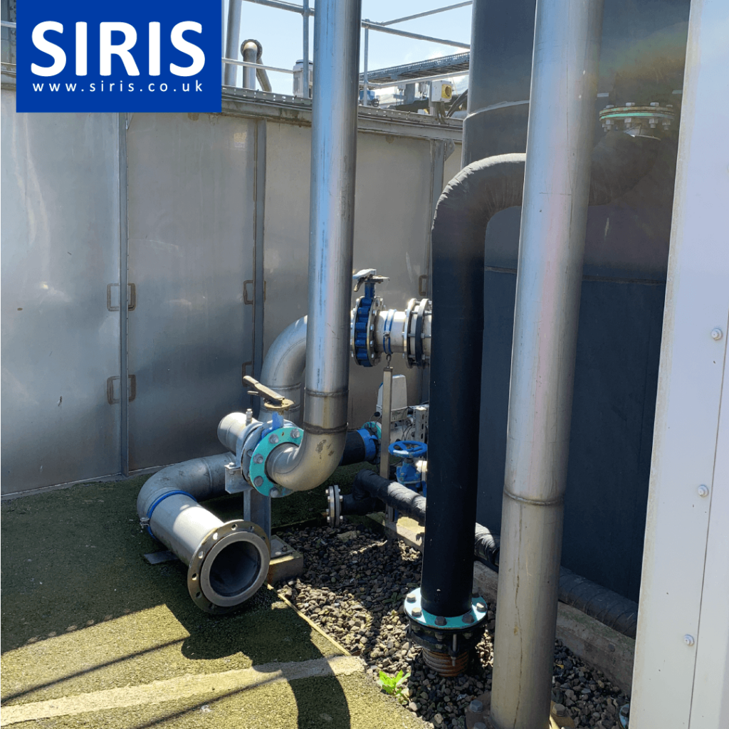
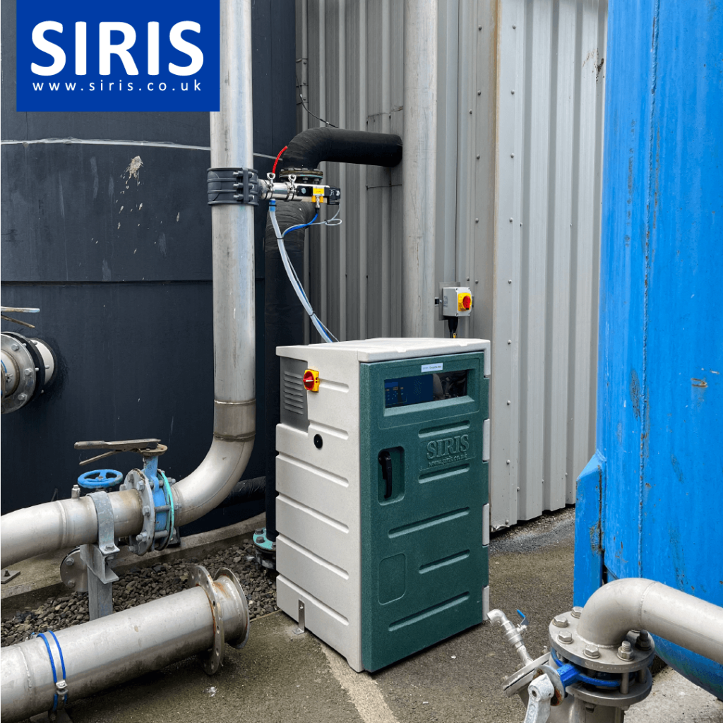
Our food factory client required two new flow system installations for their site in South West England.
Work Completed
The first install was for a full new flow system, comprising of:
– Flow meter
– Ultrasonic transducer and bracket
– A new primary device of a rectangular weir on a SIRIS carrier board (suitable for flows up to 50 l/s
The second install was also for a flow system as per the above specification but did not require a new primary device as the current one met MCERTS standards.
The Outcome
The client now has confidence in a system that will not only meet their internal reporting and monitoring needs but will also ensure they meet compliance standards for MCERTS inspections and any associated audits.
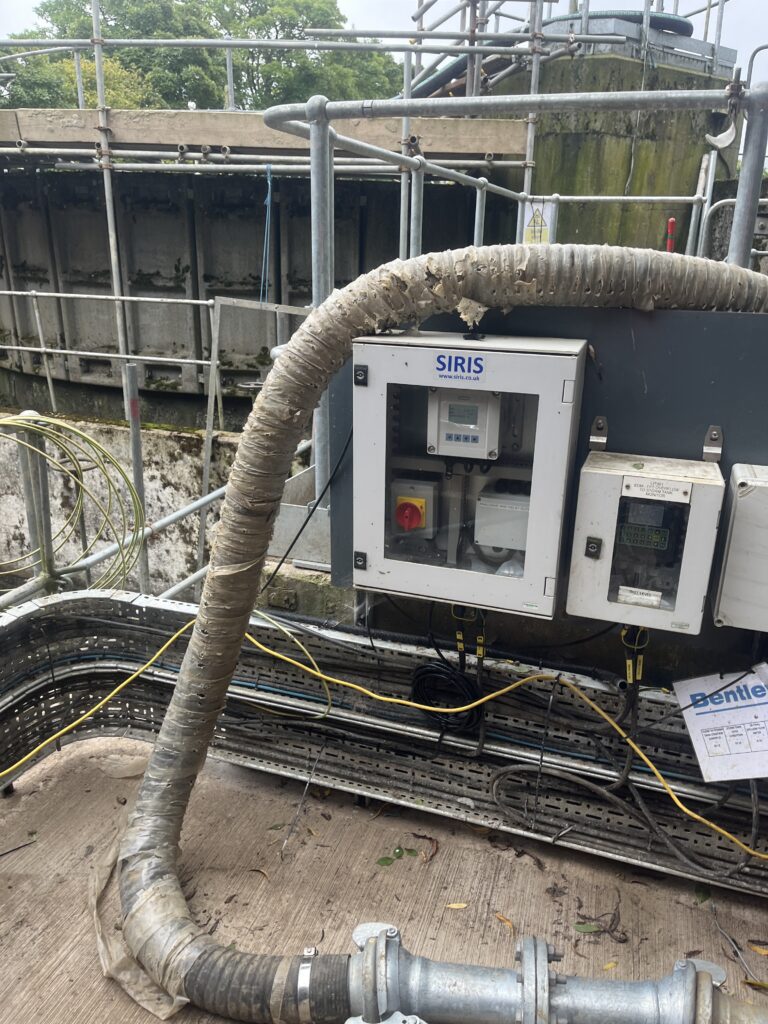
Before
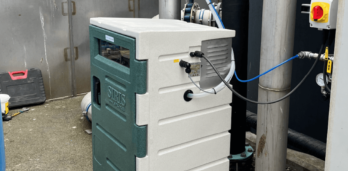
After
Require a new flow system?
Our team has the solution for you. Talk to us today.
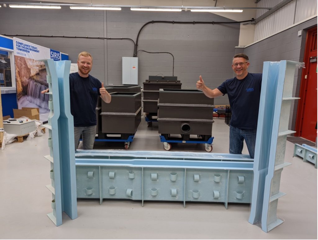
At SIRIS we are driven by innovation and continuous improvement in our products and processes. Flumes are no exception, with this component being an integral part of the SIRIS product portfolio and many flow monitoring system solutions.
Flume Innovations
Our team has been listening hard to the ongoing needs of clients and modern-day flume requirements and we have consequently implemented two innovations to our range of flumes.
A New, Deeper Flume Option
During a routine post-installation verification check, one of our experienced project engineers quickly identified issues within this flow meter installation. It rapidly became apparent that the third-party contractor had not installed the meter correctly, meaning that incorrect measurements were pulling through to the data feed.
Our engineer was able to recognise that the Sensorprom (the part of the flow meter sensor that carries the unit calibration value) had not been installed correctly and had defaulted to factory settings. This included the incorrect bore size, the calibration (cal) factor and the excitation value.
During our initial response our engineer was able to adjust and reset the flow meter to the unique original Sensorprom characteristics. On adjustment the meter significantly changed its flow reading and this was checked against a secondary time of flight reference.
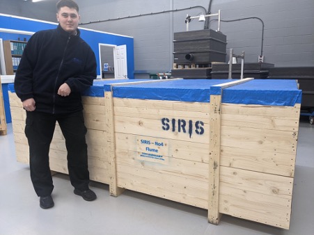
Boxed Flumes
We now offer our flumes in protective boxed packaging. This means that they are better protected against damage and the elements, as well as being kept secure during transit.
The hardwearing purpose-built boxes protect the flumes against knocks and scratches and even have a built-in tarpaulin to allow safe storage on site in wet weather conditions.
Our SIRIS boxed flumes are available in a range of sizes and are in stock for immediate delivery.
We are encouraging our customers to return the boxes to SIRIS to be re-used and help reduce our environmental footprint. Instructions explaining how to arrange the return of the box are included in all shipments.
Lee, Project Engineer
“We are always seeking to innovate and respond to our client needs. These two new additions to our flumes range allow us to further improve our service offering to the market. We are proud of our team here – there is a natural curiosity to investigate possible solutions and find new answers to existing challenges. This is what helps us to stay at the forefront of our industry.”
Require flumes or full flow monitoring system?
Our team has the solution for you. Talk to us today.
An end user client was experiencing issues with data accuracy after the installation of a flow meter by a third-party contractor. Our team was able to swiftly identify and adjust set-up to ensure the data they received was correct.
The Client Needs
It was identified that an end user dairy producer was experiencing issues with accuracy of data outputs from their newly-installed electromagnetic flow meter. It was important that the cause was identified and rectified so that their data was correct, particularly as this was used for charging purposes.
Our Response
During a routine post-installation verification check, one of our experienced project engineers quickly identified issues within this flow meter installation. It rapidly became apparent that the third-party contractor had not installed the meter correctly, meaning that incorrect measurements were pulling through to the data feed.
Our engineer was able to recognise that the Sensorprom (the part of the flow meter sensor that carries the unit calibration value) had not been installed correctly and had defaulted to factory settings. This included the incorrect bore size, the calibration (cal) factor and the excitation value.
During our initial response our engineer was able to adjust and reset the flow meter to the unique original Sensorprom characteristics. On adjustment the meter significantly changed its flow reading and this was checked against a secondary time of flight reference.
The Outcome
The end user now has confidence that their flow data being recorded and subsequently billed against is correct.
Lee, Project Engineer
“It is critical that any flow meter installation is carried out in line with the manufacturer’s recommendations and industry best practice, and that an independent verification process takes place. Flow monitoring systems are complex and in the case of electromagnetic flow meters there are often issues that would only be obvious to an experienced user. We would advise any end users using contractors to carry out appropriate due diligence on the experience and knowledge of a potential flow monitoring system installer. We are always here to provide advice and support.”
Require flow meter calibration?
Our team has the solution for you. Talk to us today.
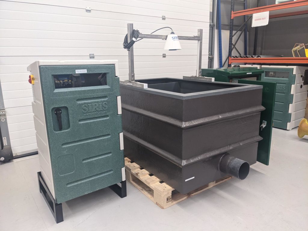
Our client, a chemical ingredients manufacturer, recently required a trade effluent flow & monitoring system in order to comply fully with regulatory discharge requirements.
Specification & Installation
To specify the correct system our team confirmed detailed information unique to the site. This included land layout and location, flow volumes and discharge limits, the nature of discharge and upstream hydraulic levels. This information is critical and helps ensure the “correct” system is specified in the first instance.
Our from-scratch solution included:
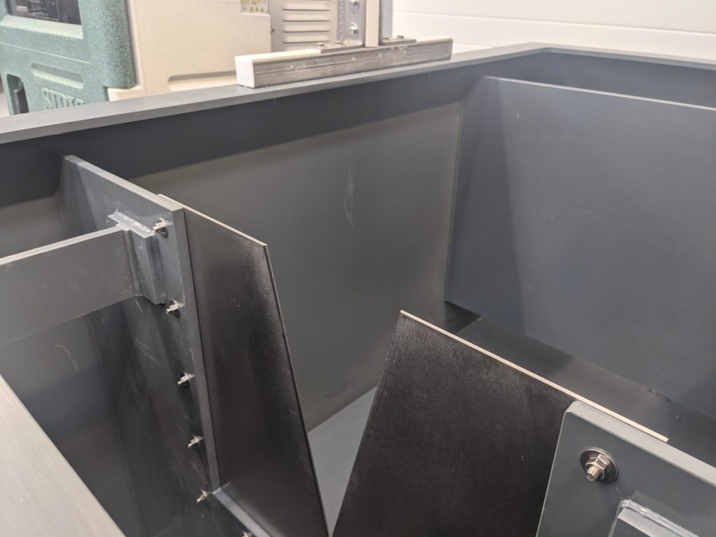
• Full flow monitoring system comprising: small weir tank with 28º4′ V-Notch thin plate weir and ultrasonic open channel flow meter
• Partech 7300w2 ph and temperature monitor
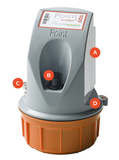
• Point orange cloud-based data logger
• SIRIS 4-bottle vacuum sampler
Production is now complete and the entire system is ready to ship to the customer. Once installed on site by the client, SIRIS engineers can attend to check the calibration and ensure everything is operating correctly. This would include site calibration of all the instrumentation.
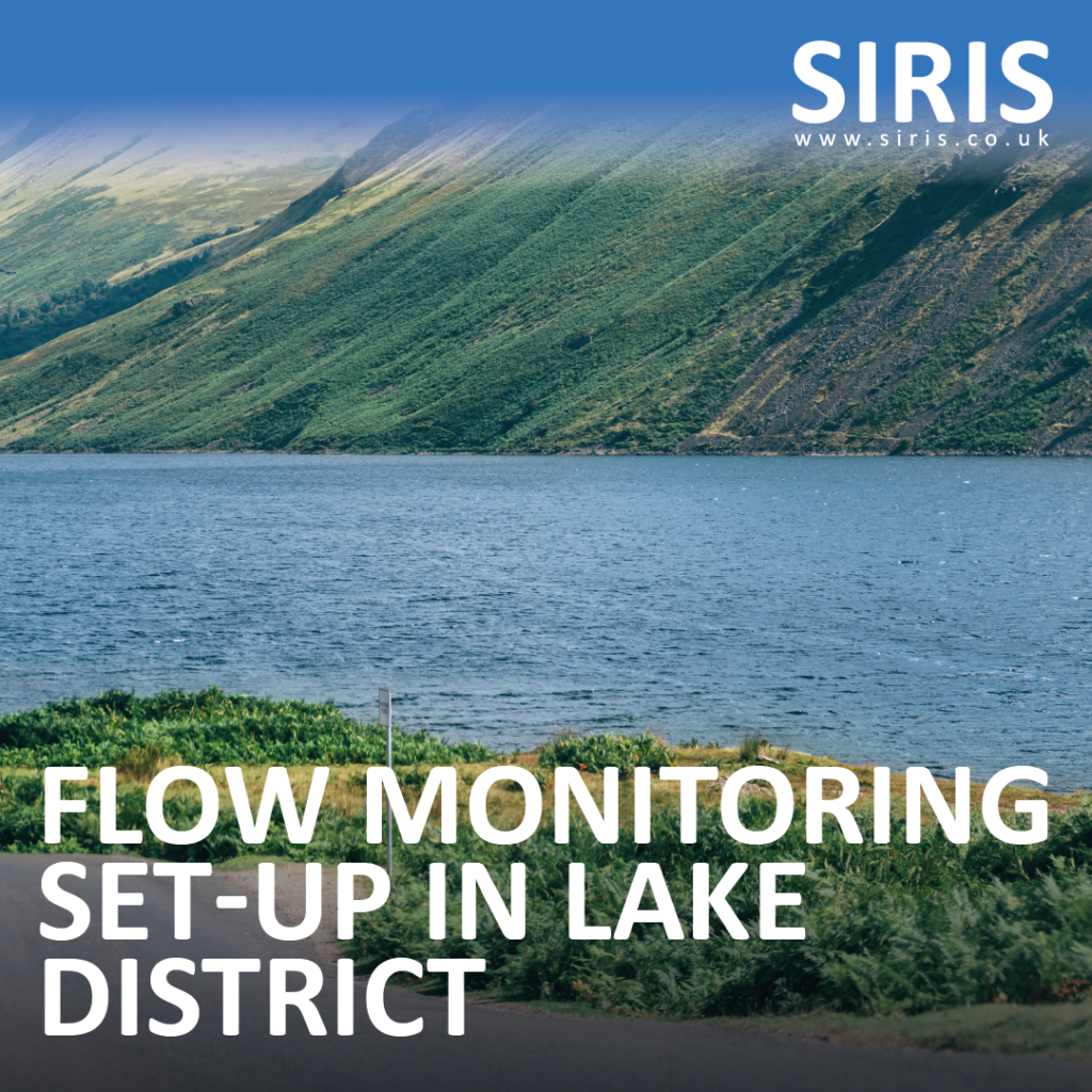
Flow Monitoring Solution for a National Park holiday resort
Our partner commercial drainage specialist Metro Mechanical asked for our help to find a suitable flow monitoring set-up that preserved the natural beauty of a unique National Park setting and provided the end customer with the flow data they needed.
The Challenge
The end customer was a holiday resort in a scenic location within the Lake District National Park. They process high volumes of waste and are charged by volume by the water company, however they didn’t have any way of measuring the amount they were using.
The project was further complicated by a lack of mains power to the remote site.
Alistair, SIRIS Projects
“The client needed a solution that not only provided accurate and reliable data provision, but was sympathetic to the aesthetics of the surrounding environment.”
The Solution
We designed and installed an electromagnetic battery-powered solution, which allowed the customer to monitor its flow data via the cloud without any power. Metro Mechanical built a chamber that allowed access to the flow meter, with a lid enabling it to blend into its scenic surroundings and avoid impacting the landscape.
The Result
We were able to provide a solution that not only ensured effective flow monitoring but also ensured the preservation of the natural beauty of the National Park setting.
Data Logging Solution
Require Flow Monitoring?
Do you have a flow meter monitoring requirement? Contact us to understand how you can quickly get a solution to your project.
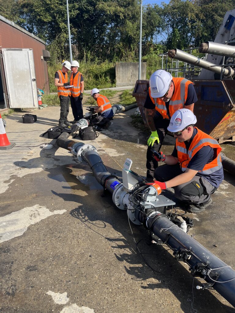
We helped this contractor ensure their project was designed and installed within the correct parameters for the rate of flow within the sewage treatment works.
The Challenge
A UK contractor delivering a project at a sewage treatment works needed to better understand the rate of flow into the works, in order to ensure installations were designed and fitted to the right size and specification.
The situation did not require a permanent installation, but a reliable solution that would give accurate data on the rate of flow into the sewage treatment works.
Alistair, SIRIS Projects
“It was vital that this client was able to build an accurate picture of the flow rate so that they could specify the correct works and installation for the end customer. We worked quickly to bring them a solution that was not only reliable, but also delivered the data in a way that was easily understood and decisions could be made.”
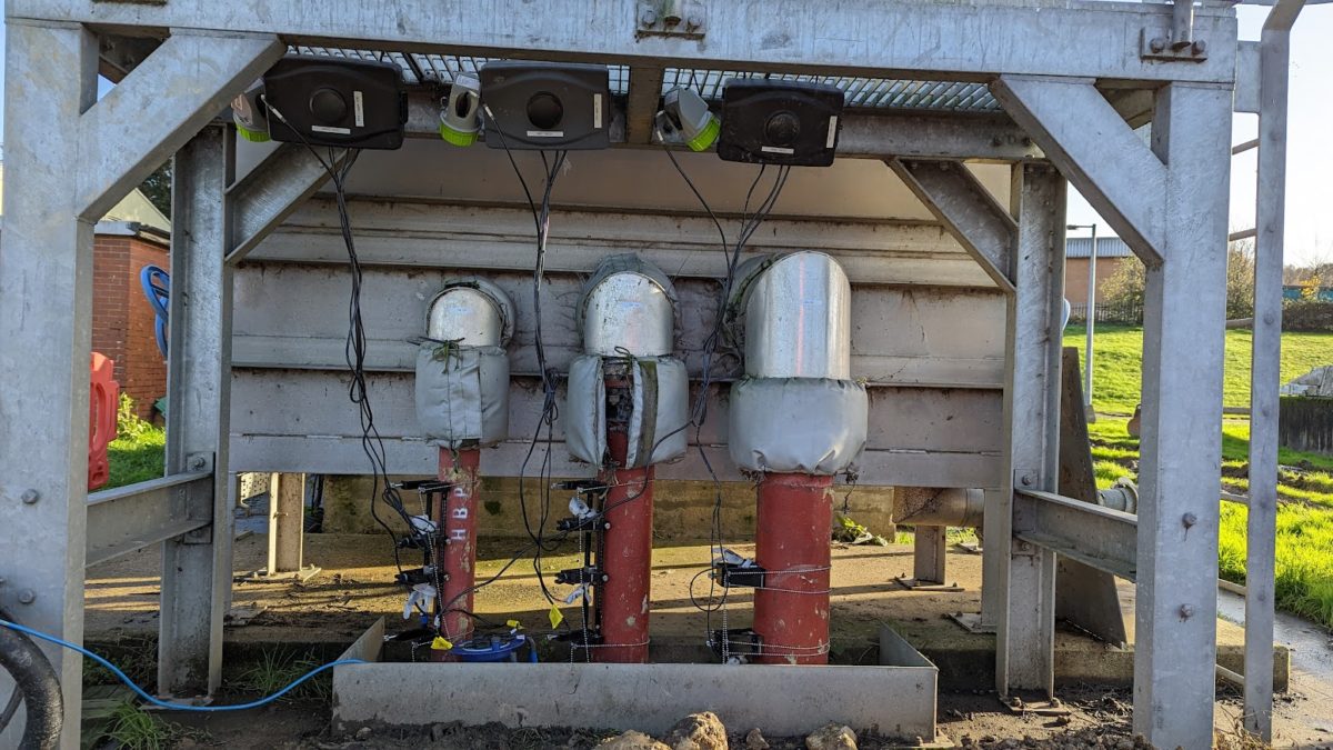
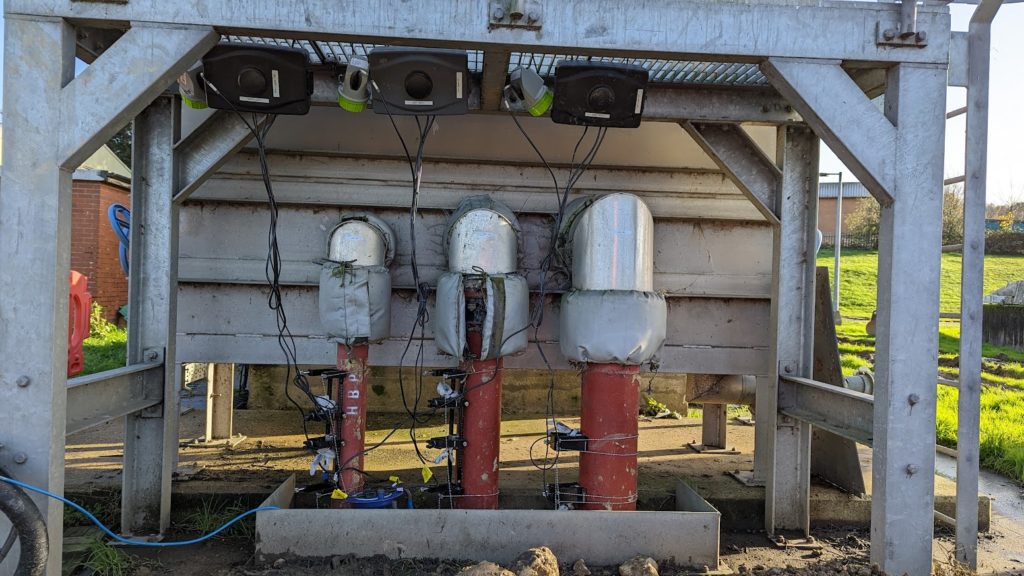
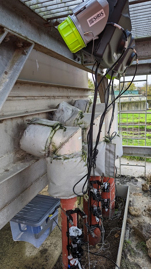
The Solution
Our team worked with the contractor to understand requirements before proposing and installing a solution that comprised of time-of-flight meters on three lines within the works. Pre-work included checking return pump flows to ensure adequate conditions within the pipe for the installation of the meters. Adverse weather conditions meant that the sensors had to be adequately protected from the elements. The meters were then calibrated and left to collect data over a number of weeks in order to build a reliable data picture of the rate of flow. Each flow meter was connected to data loggers, which then sent measurements to the cloud.
The Result
Key to success of this project was the client’s ability to view the data visually. All SIRIS flow meter hires include remote access from any device to the data, which is not only available in its raw format, but also in pre-set and standardised visual formats that are easily understood by most stakeholders.
The contractor was able to accurately understand the rate of flow throughout the works and therefore specify and install the correct solution for the end client.
Flow Meter Hire?
Do you have a flow meter hire requirement? Contact us to understand how you can quickly get a solution to your project.


