Effluent flow meters are crucial instruments in industrial and environmental settings, providing accurate measurement and monitoring of wastewater discharge. Most UK businesses subject to consent to discharge permit requirements will be required to record and submit the volume and quality of the wastewater they are producing – and will require a wastewater flow meter of some description for this purpose. Designed to ensure compliance with regulatory standards, these meters offer real-time data on flow rates, helping companies optimise processes and minimise environmental impact.
If the responsibility for effluent flow measurement is yours, then it is important that you understand why certain flow meters should be used in particular conditions.
With precision engineering and advanced technology, effluent flow meters can empower your business to make informed decisions, safeguarding both operational efficiency and environmental safeguarding. This guide to types of flow meters explains the different types of effluent flow meters that are available and what to consider when both selecting and maintaining your flow measurement solution.
Where are Effluent Flow Meters Used?
Effluent flow meters are utilised across various industries where monitoring and managing wastewater discharge are critical. Some of the key industries commonly using effluent flow meters include:
- Local Authority Wastewater Treatment: Water companies use effluent flow meters to monitor the flow of wastewater within sewage collection systems and wastewater treatment plants to ensure compliance with regulatory standards and optimise treatment processes.
- Industrial Manufacturing: Industries such as chemical manufacturing, food & beverage processing, pulp & paper production and pharmaceutical manufacturing use effluent flow meters to measure and control the discharge of process wastewater, ensuring compliance with environmental regulations and minimising the environmental impact of their operations.
- Mining and Mineral Processing: Mining operations and mineral processing plants use effluent flow meters to monitor and manage the discharge of wastewater generated during various mining and processing activities, including ore extraction, crushing, grinding and mineral beneficiation.
- Power Generation: Power plants, including thermal power plants and nuclear power plants, use effluent flow meters to monitor the discharge of cooling water and wastewater generated during power generation processes, ensuring compliance with environmental regulations and minimising the impact on aquatic ecosystems.
- Oil and Gas Production: Upstream oil and gas production facilities, including oil wells, gas wells, and production platforms, use effluent flow meters to monitor the flow of produced water, wastewater and effluent streams , generated during oil & gas extraction and processing operations.
- Refining and Petrochemicals: Refineries and petrochemical plants use effluent flow meters to monitor and control the discharge of wastewater and effluent streams generated during refining and chemical processing operation, again to ensure regulatory and environmental compliance.
Different Types of Effluent Flow Meters
Each type of flow meter has its advantages and limitations, and the selection depends on factors such as the fluid properties, flow conditions, accuracy requirements and budget constraints. Effluent flow meters are typically split for suitability for either open channels or closed pipes.
Ultrasonic Flow Meters
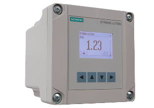
Ultrasonic flow meters provide a reliable and accurate method of measurement in open conditions, used as part of an open channel flow measurement system and should be used alongside a “primary flow device” such as a flume or a weir.
The typical methodology for measuring flow in an open channel is to measure the depth of the liquid in the channel using the ultrasonic sensor upstream of the weir or a flume, before this depth is then used to calculate the flow rate. This method relies on the flumes or weirs being constructed and installed in a manner that ensures the water depth at the point of measurement (the gauge point) is smooth and controlled.
The ultrasonic flow meter transmits continuous high-frequency sound pulses, waiting for an “echo” to determine the exact depth of the water upstream the flume or weir.
The exact variation of formula used to then calculate the flow will differ depending on the specific primary flow device used.
- These meters can handle a variety of effluent types, dependent upon the flow structure through which it is passing
- When installed and calibrated correctly, ultrasonic flow meters can provide highly accurate flow measurements. Advanced models compensate for temperature variations that affect the speed of the ultrasonic signal
- They perform consistently across a wide range of flow rates and conditions, making them reliable for long-term monitoring
- Very durable and long-lasting
- Installation of ultrasonic flow meters is generally straightforward and flexible
- Many ultrasonic flow meters come with smart interfaces that provide real-time data and diagnostics, which can be crucial for process control and decision-making
- Can be impacted by certain environmental conditions such as temperature, though sun shades can be used to mitigate this
- Correct specification, calibration and installation is essential to accuracy of data and success of this flow meter
Area Velocity Flow Meters
Area velocity flow meters calculate flow rate by understanding the cross section and nature of the channel in which it is measuring depth and velocity. There are two types of this flow meter: non-contact and wetted. The wetted version is often placed on the bed of a channel and has historically used the Doppler effect to measure the velocity. Non-contact types are mounted above the channel and beam a radar (surface velocity only) or laser (surface and sub-surface velocities) to measure the velocity, with the depth often calculated using a look-down ultrasonic sensor. An area velocity flow meter for effluent water operates on the area x velocity method to calculate flow rate. This shift in frequency is used to provide a flow velocity measurement.
Key factors in selection:
- The key rationale for use of an area velocity flow meter is the speed and convenience with which it can be installed
- Area velocity flow meters can offer a good short-term fix and are often used for surveys
- It is easy to install and often has no disruption to the flow
- Although they reduce the initial investment needed with traditional open channel flow system measurement, their comparable accuracy in non-favourable conditions and their ability to be independently verified is still debatable. Their choice should therefore be considered carefully for long-term value for money.
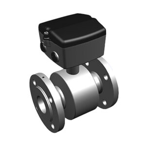
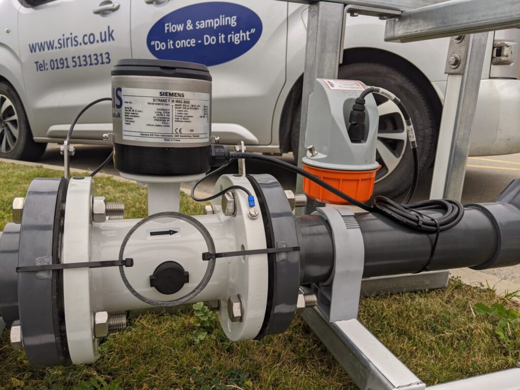
Electromagnetic Flow Meters
Designed for measuring liquid flow within an enclosed pipe, electromagnetic flow meters measure the voltage produced by a conductor (the wastewater) moving through a magnetic field. The voltage is proportional to the velocity of the conductor and can be converted to a flow rate. This calculation works on the principle of Faraday’s Law of electromagnetic conduction. Also commonly known as “magmeters”, they require a conducting fluid such (in this instance effluent) and a non-conducting pipe liner. These meters are popular and provide a highly accurate option for wastewater flow measurement.
Key factors in selection:
- Electromagnetic flow meters can be an ideal solution where pressure loss should be avoided as they can provide an unobstructed flow path when installed
- They are a low maintenance option with no moving parts making them robust. However there should be a regular schedule of maintenance where the internal pipe bore is cleaned and inspected.
- They are robust and resistant to factors such as corrosion, abrasion, and temperature fluctuations
- Many electromagnetic flow meters can measure flow in both directions, allowing for versatility in monitoring fluid movement within pipelines and processing systems.
- Accurate installation by qualified experts is essential for their successful use
- The meter must run full and be correctly earthed to the fluid to remove stray voltage
Coriolis Flow Meters
This a type of flow meter that operates based on the principles of the Coriolis effect, which is a physical phenomenon observed in rotating reference frames.
The core component of a Coriolis flow meter is a vibrating tube or tubes through which the fluid flows. These tubes are typically made of metal and are arranged in a specific configuration. The vibrating tubes are set into motion by a drive system, causing them to oscillate at their natural frequency. As the fluid flows through the vibrating tubes, it causes a deflection in the tube’s motion due to the Coriolis effect. The deflection is proportional to the mass flow rate of the fluid. Sensors located at different points along the vibrating tubes measure the phase shift between the input and output vibrations caused by the fluid flow. This phase shift is directly proportional to the mass flow rate of the fluid. The measured phase shift is then converted into a flow rate value using calibration factors specific to the Coriolis flow meter.
Overall, while Coriolis flow meters offer excellent accuracy and direct mass flow measurement capabilities, their higher cost, susceptibility to fouling, and maintenance requirements make them less suitable for effluent flow measurement applications in wastewater treatment plants. Other flow meter types, such as electromagnetic and ultrasonic flow meters, are often preferred for their cost-effectiveness, reliability, and suitability for effluent flow measurement.
Key factors in selection:
- Unlike many other flow meter types that measure volumetric flow, Coriolis flow meters directly measure mass flow, making them suitable for applications where accurate mass measurement is required
- Coriolis flow meters typically have minimal pressure drop compared to other flow meter types, making them suitable for applications where maintaining a consistent pressure is important
- Coriolis flow meters can be used for various fluids, including liquids, gases, and multiphase flows, making them versatile for different industries and applications
- Coriolis flow meters tend to be more expensive than other types of flow meters, such as electromagnetic or ultrasonic flow meters. Effluent flow measurement applications often prioritize cost-effectiveness, making Coriolis meters less attractive.
- Coriolis flow meters can be bulkier and heavier compared to other flow meter types, which can make them more challenging to install and maintain, especially in retrofit or existing effluent flow measurement systems
- Effluent streams from wastewater treatment processes can contain solids, debris, and other contaminants that may cause fouling or build-up on the surfaces of the flow meter. Coriolis meters, with their intricate vibrating tube design, may be more susceptible to fouling, leading to inaccurate measurements and increased maintenance requirements.
- While Coriolis flow meters offer excellent accuracy across a wide range of flow rates, they may have limitations in turndown ratio compared to other flow meter types. Effluent flow rates in wastewater treatment plants can vary widely, and flow meters with high turndown ratios are often preferred for flexibility in measurement.
- Coriolis flow meters may require more frequent maintenance compared to other flow meter types due to their intricate design and moving parts. Effluent flow measurement systems in wastewater treatment plants typically prioritize reliability and low maintenance requirements.
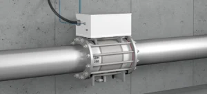
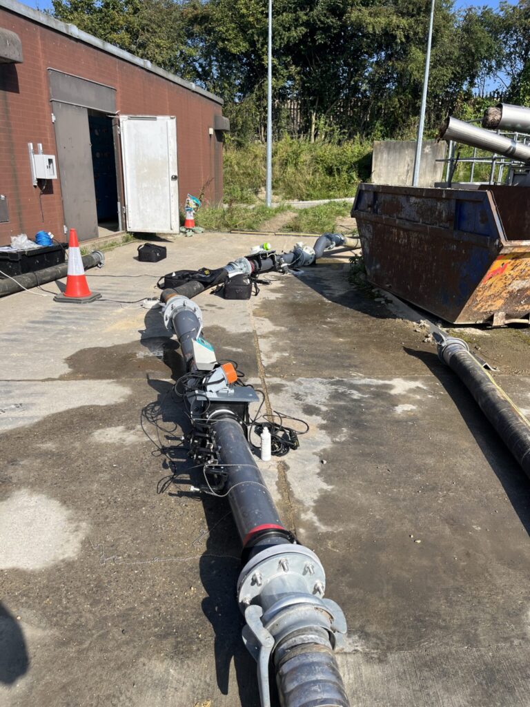
Clamp-On Ultrasonic Flow Meters
A clamp-on ultrasonic flow meter is a convenient method for flow measurement as they do not require the pipe to be opened up for their installation.
They work using the “transit time” theory, where the difference in transit time between those pulses going in the direction of flow, versus those going against the direction of flow, is measured. This measurement of difference is then used to give the liquid average velocity along the path of the ultrasonic pulse. Using these transit times and knowing the area of the pipe it is possible to measure flow rate.
These units are also available for hire and can provide a temporary flow measurement solution.
Key factors in selection:
- Their main advantage is the ease of installation, as they are attached onto the outside of the pipe. They measure flow using external sensors that clamp onto the outside of the pipe. This means there is no need to cut the pipe or halt the flow for installation, reducing downtime and potential contamination.
- Correct installation is key to ensure there are no air gaps between the clamp and the pipe
- Where cost or time of installation for an electromagnetic flow meter is prohibitive then they provide a convenient alternative
- With no pressure drop or energy loss, a wide turn-down ratio and no need to cut the pipe or stop the flow, installation is easy and maintenance can be minimal
- Some models can even calculate temperature of the fluid
- Ultrasonic meters are effective on a wide range of pipe diameters and materials, from small plastic tubes to large metal pipes
- Since they do not require opening the pipeline and can be operated remotely, ultrasonic meters are suitable for use in hazardous environments where effluent might be toxic or highly corrosive
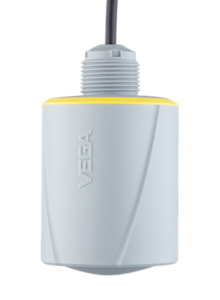
Radar Level Flow Meters
Radar flow meters give reliable and accurate results in open conditions, used as part of an open channel flow measurement system
The meters are designed to be used alongside flumes/weirs in a fully-designed flow system, emitting a continuous radar signal – via the antenna system – that is reflected on the surface of the liquid to produce an echo to determine the height of the liquid as it flows through the flume or weir. The meter then calculates the level of liquid using the running time of the microwave signals and the entered tank height.
Key factors in selection:
- These meters can handle a variety of effluent types, dependent upon the flow structure through which it is passing
- When installed and calibrated correctly, radar flow meters can provide highly accurate flow measurements
- They perform consistently across a wide range of flow rates and conditions, making them reliable for long-term monitoring
- Very durable and long-lasting
- Installation of radar flow meters is generally straightforward and flexible
- Many radar flow meters come with smart interfaces that provide real-time data and diagnostics, which can be crucial for process control and decision-making
- Correct specification, calibration and installation is essential to accuracy of data and success of this flow meter
Venturi Flow Meters
The Venturi flow meter consists of a converging section where the pipe diameter narrows, a throat (the narrowest part), and a diverging section where the pipe diameter expands again. This design creates a pressure differential as the fluid flows through the meter. As the effluent enters the converging section of the Venturi meter, its velocity increases, leading to a decrease in pressure at the throat relative to the wider sections of the pipe. This pressure drop is proportional to the flow rate of the fluid, according to Bernoulli’s principle.
A Venturi flow meter is an effective tool for measuring the flow rate of effluent (wastewater) in various industrial and treatment settings and is used to measure the volume of wastewater flowing into treatment plants as well as the monitoring of effluent flow discharge.
Pressure sensors or taps are located at the wider upstream section and at the throat. These sensors measure the high and low pressures of the flowing effluent. The flow rate can be calculated using the differential pressure (the difference between the upstream and throat pressures), the cross-sectional area of the pipe at the measurement points, and the fluid properties such as density and viscosity.
Key factors in selection:
- Venturi meters provide high accuracy in flow measurement, which is vital for process control and regulatory compliance
- The design of the meter, with no moving parts and a simple constriction in the pipe, means it is less likely to be clogged by solids in the effluent, reducing maintenance needs
- The Venturi design allows for flow measurement without intruding significantly into the flow path, reducing the risk of obstruction and the associated maintenance
- Venturi meters are effective in high-pressure and high-velocity flow conditions, making them suitable for a wide range of industrial applications
- Typically made of robust materials, Venturi meters can withstand harsh environmental conditions and aggressive fluids
- Proper calibration and setup are crucial for accurate measurements. Incorrect installation angle or improper calibration can lead to significant measurement errors.
- The constriction in the flow path causes a pressure drop, which is not fully recovered as the fluid exits the meter. This results in a permanent energy loss, which can be a disadvantage in systems where maintaining energy efficiency is critical.
- Venturi meters can be expensive to install, particularly for large pipe diameters. The cost includes not just the meter but also installation and setup.
- They can handle various flow conditions and types of effluent, including those with suspended solids
- While Venturi meters can handle some amount of suspended solids, they are not ideal for effluent with high levels of solids or very viscous fluids, as these can affect the accuracy of the pressure differential measurement
- A Venturi meter typically requires a straight pipe run to stabilize flow before and after the meter. This can be a limitation in facilities with space constraints.
How do flow meters work?
Effluent flow meters work based on various principles to measure the flow rate of wastewater or effluent streams.
The Time of Flight Principle
The time-of-flight principle in flow meters refers to the measurement technique based on the travel time of a signal or substance between two points in a flow stream. In this principle, a signal or substance is emitted into the flow, and its travel time between two points is measured. By calculating the time taken for the signal or substance to travel a known distance, the flow velocity or flow rate can be determined.
For example, in ultrasonic flow meters, sound waves are transmitted upstream and downstream in the flow. The difference in time taken for the sound waves to travel with and against the flow direction is used to calculate the flow velocity. By combining this velocity measurement with the cross-sectional area of the flow, the volumetric flow rate can be determined.
Similarly, in electromagnetic flow meters, a magnetic field is applied across the flow stream, and electrodes measure the induced voltage generated as the conductive fluid flows through the magnetic field. The time it takes for the fluid to travel between the electrodes is directly related to the flow velocity, allowing for accurate flow rate measurement.
Overall, the time-of-flight principle provides a reliable method for measuring flow rates in various types of flow meters, enabling precise monitoring and control of fluid processes in industrial applications.
Flow meters that utilise the time-of-flight principle include:
- Ultrasonic Flow Meters: These meters measure the time it takes for an ultrasonic signal to travel between two points in a flowing fluid. By comparing the transit times of signals traveling upstream and downstream, the flow velocity can be determined.
The Doppler Effect
The Doppler effect principle in flow meters is based on the frequency shift of a transmitted signal caused by the movement of particles or objects within a fluid.
Doppler flow meters are particularly useful in applications where the fluid contains suspended particles or air bubbles, making them ideal for measuring the flow of liquids containing solids or gases, such as wastewater or slurry.
Overall, the Doppler effect principle provides a reliable method for measuring flow velocity in various fluid systems, offering non-intrusive and accurate flow measurement solutions.
It works in the following way:
- Transmitted Signal: A transmitter emits a continuous wave signal, typically ultrasound, into the flowing fluid.
- Interaction with Flowing Particles: As the signal encounters particles or objects moving within the fluid, such as suspended solids or air bubbles, its frequency is altered due to the Doppler effect. If the particles are moving toward the transmitter, the frequency of the signal increases; if they are moving away, the frequency decreases.
- Received Signal Analysis: A receiver detects the altered frequency of the signal after it has interacted with the flowing particles.
- Calculation of Flow Velocity: By analysing the frequency shift between the transmitted and received signals, the flow velocity of the fluid can be determined. The greater the frequency shift, the faster the flow velocity.
Flow meters that utilise the Doppler effect include:
Ultrasonic Flow Meters: These meters emit ultrasonic signals into the flow and analyse the frequency shift of the reflected signals off moving particles or bubbles within the fluid. By measuring this frequency shift, the flow velocity can be determined.
Orifice Plate Flow Meter Approach
An orifice plate flow meter is a simple yet effective device used to measure the flow rate of a fluid within a pipeline. It consists of a thin plate with a hole (or orifice) drilled through its centre, placed perpendicular to the flow direction within the pipeline.
Orifice plates are widely used in industrial applications due to their simplicity, reliability, and low cost. However, they can introduce a permanent pressure loss in the pipeline and are not suitable for measuring low flow rates or fluids with high viscosity or entrained solids.
An orifice plate flow meter works as follows:
- Installation: The orifice plate is installed in the pipeline, typically between flanges, where it causes a constriction in the flow path
- Pressure Tapings: To measure the pressure drop accurately, pressure tapings are installed upstream and downstream of the orifice plate. These tapings allow for the measurement of the differential pressure across the orifice.
- Flow Measurement: As the fluid flows through the pipeline, it passes through the orifice, causing a pressure drop across the plate. This pressure drop is directly proportional to the flow rate of the fluid.
- Calculation: Using the measured pressure drop across the orifice plate and known physical properties of the fluid and orifice, (such as density and diameter), the flow rate can be calculated using standardised equations e.g. Bernoulli’s equation
Orifice plates are found in the following flow meter types:
- Orifice Flow Meters: These flow meters specifically utilise an orifice plate as the primary flow measurement element. The orifice plate creates a differential pressure across the flow stream, which is correlated with the flow rate.
- Differential Pressure Flow Meters: Orifice plates are also used in differential pressure (DP) flow meters, such as orifice DP flow meters, venturi meters, and flow nozzles. In these meters, the orifice plate creates a pressure drop, and the differential pressure across the orifice is measured to determine the flow rate.
- Primary Elements in Multi-Variable Flow Meters: Orifice plates can be part of multi-variable flow meters that measure multiple parameters simultaneously, such as flow rate, pressure, and temperature. In such cases, the orifice plate serves as the primary flow measurement element.
Faraday’s Law
Faraday’s law of electromagnetic induction is a fundamental principle in physics that describes the relationship between a changing magnetic field and the induction of an Electromotive Force (EMF) or voltage in a conductor. In the context of flow meters, Faraday’s law is applied in electromagnetic flow meters to measure the flow rate of conductive fluids.
Overall, Faraday’s law of electromagnetic induction serves as the underlying principle for the operation of electromagnetic flow meters, allowing for accurate and reliable measurement of flow rates in a wide range of conductive fluids.
Faraday’s law is used with flow meters in the following way:
- Principle: Faraday’s law states that when a conductor (such as a fluid) moves through a magnetic field, and when there is a change in the magnetic field surrounding the conductor, an Electromotive Force (EMF) is induced in the conductor.
- Application in Flow Meters: In electromagnetic flow meters, a magnetic field is generated across the flow stream by energising coils or magnets located outside the flow tube. As the conductive fluid flows through the magnetic field, it cuts across the magnetic field lines, resulting in a voltage being induced in the fluid, perpendicular to both the flow direction and the magnetic field.
- Measurement of Induced Voltage: Electrodes or sensors are placed in the flow meter to measure the voltage induced in the fluid. This induced voltage is directly proportional to the flow velocity of the fluid, according to Faraday’s law.
- Calculation of Flow Rate: By measuring the induced voltage and knowing the properties of the fluid and the magnetic field, such as conductivity and strength, the flow rate of the fluid can be calculated using mathematical relationships derived from Faraday’s law and other principles of electromagnetism.
Flow meters that utilise Faraday’s Law include:
- Electromagnetic Flow Meters: These meters utilise Faraday’s law of electromagnetic induction. A magnetic field is created, perpendicular to the flow path, and as the conductive fluid flows through this field, an Electromotive Force (EMF) is induced. The EMF is directly proportional to the flow velocity, therefore allowing for accurate flow rate measurement.
The Coriolis Effect
The Coriolis effect is a phenomenon that occurs because of the Earth’s rotation and affects the motion of objects moving relative to the Earth’s surface. It is named after the French mathematician Gaspard-Gustave de Coriolis, who described it mathematically in 1835.
Due to the Earth’s rotation, objects in motion appear to follow a curved path rather than a straight line. In the Northern Hemisphere, this deflection is to the right, while in the Southern Hemisphere, it is to the left. This apparent deflection is strongest at the poles and diminishes to zero at the equator because the Earth rotates faster at the equator than at higher latitudes.
In relation to flow monitoring, the Coriolis effect refers to the use of Coriolis force in measuring the mass flow rate of a fluid moving through a pipe. Coriolis flow meters typically consist of one or more vibrating tubes through which the fluid passes. These tubes are caused to oscillate in an angular harmonic oscillation due to an external actuator. When there is no fluid flow, the vibrations of the tube are symmetrical and uniform. However, as fluid begins to flow through the tube, the motion of the fluid particles also induces a rotational motion due to the Coriolis force. The Coriolis force causes the tube to twist slightly in response to the mass flow of the fluid moving through it. This twist results in a phase shift between the inlet and outlet sides of the vibrating tube. Sensors positioned at points along the tube detect this phase shift, which is proportional to the mass flow rate of the fluid.
Flow meters that utilise the Corilois effect include:
Coriolis Flow Meters: Coriolis flow meters use the Coriolis effect, where a vibrating tube is affected by the inertia of the fluid flowing through it. The phase shift between the inlet and outlet vibrations is proportional to the mass flow rate, allowing for direct mass flow measurement.
Bernoulli’s Principle
Bernoulli’s principle is a fundamental concept in fluid dynamics that describes the behaviour of fluid under varying conditions of flow and pressure. Developed by Daniel Bernoulli in the 18th century, it states that in a flowing fluid (liquid or gas), an increase in the fluid’s velocity leads to a decrease in its static pressure and potential energy.
The principle is derived from the conservation of energy and can be explained as follows: when a fluid flows through a constricted area of a pipe, its speed must increase to maintain the rate of flow, because the same volume of fluid has to pass through a smaller area. According to Bernoulli’s principle, when the velocity of a fluid increases, its pressure decreases. This relationship is critical in understanding how air moves over the wing of an airplane to create lift, among other applications.
Bernoulli’s Principle is integral to the design and function of certain types of flow meters, such as Venturi meters and orifice plates. These devices utilise the fundamental concepts of Bernoulli’s equation to determine the flow rate of fluids by measuring changes in pressure within a flowing system.
Flow meters that utilise Bernoulli’s Principle include:
- Venturi Meters: These devices feature a constricted throat that narrows the flow path of the effluent. As the fluid enters the throat, its velocity increases, leading to a decrease in pressure at this point—a direct application of Bernoulli’s principle. Pressure sensors placed before and at the throat measure the pressure differential. This pressure drop, related to the velocity increase, allows calculation of the flow rate using the continuity and Bernoulli equations.
- Orifice Plates: Similar to Venturi meters, orifice plates have a hole in the middle that causes the fluid to accelerate as it passes through, decreasing the pressure across the plate. The difference in pressure between the upstream side and the downstream side of the orifice is measured. The flow rate can then be calculated from this pressure drop and the known dimensions of the orifice.
Considerations in Selection of Effluent Flow Meter
Any consent to discharge permit will require correct installation, operation and maintenance of your flow measurement system. Careful and knowledgeable selection of measurement system is important as each flow meter type varies in its suitability. When selecting an effluent flow meter type, several factors should be considered to ensure that the chosen meter meets the specific requirements of the application.
By carefully considering these factors, you can select the most suitable effluent flow meter type for your application, ensuring accurate and reliable flow measurement while meeting operational and regulatory requirements.
- Fluid Characteristics: Understand the properties of the effluent fluid, including its conductivity, viscosity, temperature, and the presence of solids or gas bubbles. Different flow meter types are suitable for different fluid characteristics.
- Flow Rate Range: Determine the expected flow rate range of the effluent. Some flow meter types are more suitable for low-flow applications, while others are better suited for high-flow conditions.
- Accuracy Requirements: Consider the required level of accuracy for flow measurement. Certain flow meter types offer higher accuracy than others, but may come with higher costs.
- Installation Conditions: Evaluate the installation environment, including factors such as available space, pipe size, orientation, and accessibility. Some flow meter types may require specific installation considerations.
- Maintenance Needs: Assess the maintenance requirements of the flow meter, including calibration, cleaning, and repair. Choose a flow meter type that aligns with the maintenance capabilities and schedule of the facility.
- Cost Considerations: Consider the initial purchase cost as well as the long-term operating and maintenance costs of the flow meter. Balance the desired features and performance with budget constraints.
- Environmental Conditions: Take into account the environmental conditions in which the flow meter will operate, including temperature extremes, exposure to corrosive substances, and potential for physical damage. Select a flow meter type that can withstand these conditions.
- Regulatory Compliance: Ensure that the chosen flow meter type meets any applicable regulatory requirements and standards for flow measurement in the specific industry or application.
The importance of correct installation and calibration
Correct installation and regular calibration of any flow meter is fundamental to confirm accuracy of data. In an ideal world a flow meter would never be affected by the conditions in which it is installed, however aggressive environments and other factors can compromise their initial installation. There is also the chance that an old system may never have been installed properly in the first instance. Although no flow measurement system is 100% accurate, with all carrying some level of uncertainty, correct calibration and robust maintenance can ensure that this level is kept to a minimum.
If you are required to install a flow meter as part of your permit or consent to discharge then it is your responsibility to ensure its correct functioning and data accuracy. Failure to confirm this could lead to penalties and fines. It is always worth the investment in a professional and informed approach from an experienced MCERTS-qualified team to guarantee long-term value for money from your flow measurement system. Not only can they ensure correct set-up, inspection and calibration, but they can also provide also provide ongoing support and guidance for when things go wrong.